


استشر الولايات المتحدة
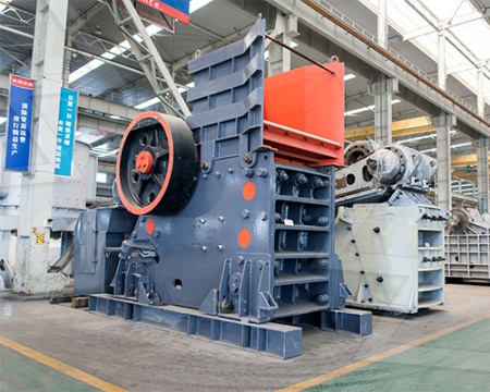
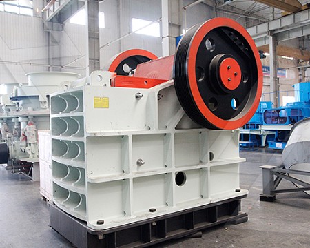
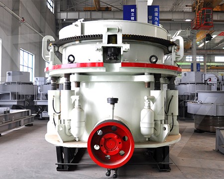
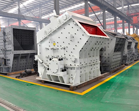
بصفتنا مصنعًا عالميًا رائدًا لمعدات التكسير والطحن ، فإننا نقدم حلولًا متطورة وعقلانية لأي متطلبات لتقليل الحجم ، بما في ذلك إنتاج المحاجر والركام والطحن ومحطة تكسير الحجارة الكاملة. نقوم أيضًا بتوريد الكسارات والمطاحن الفردية وكذلك قطع غيارها.
Crusher an overview | ScienceDirect Topics
Schematic diagram showing principle of jaw crusher showing the path of lumpy feed ore to fragmented product crushed under high pressure of fixed and moving jaws The type of1999年12月1日· The flow model provides detailed information about how different machine parameters affect the flow of the rock material through the crusher chamber From theModelling of flow in cone crushers ScienceDirect
MODELLING, SIMULATION AND OPTIMISATION OF A CRUSHING
design of a control model utilising two crusher variables and a selftuning control algorithm In this research work, a process model describing the dynamic operation of an OsbornDownload scientific diagram | Process flow sheet for the crushing tests, including sampling for laboratory testing from publication: Influence of jaw crusher parameters on the quality ofProcess flow sheet for the crushing tests, including
Schematic description of the crushing plant, (1)
Schematic description of the crushing plant, (1) primary crusher, (2) secondary crusher, (3) tertiary crushers, (4) final screens and (5) a switch for changing the process flow2016年4月14日· This flow diagram shows a threestage gravel plant schematically It shows the interrelationships and functions of the various components of the plant This sort of diagram can be used to advantageCrushing & Screening Plant Design Factors 911
A review of modeling and control strategies for cone
2021年8月15日· This work opens with a brief review of the mechanical principles of cone crushers Then, in the following sections, works available in the cone crusher literature,Download scientific diagram | Layout of a fourstage crushing plant for ballast production from publication: Cone Crusher Performance | PhD Thesis Cone crushers are used by both theLayout of a fourstage crushing plant for ballast
The flowchart of crushing process with onestage and
This work will assist to predict the efficiency and performance of a jaw crusher when used to crush different choke feed levels and effective reduction ratios as well as the influence of coalillustrating flow diagrams of the system have also been enclosed to enhance clarity of the text Standard Design Criteria/Guidelines for Balance of Plant of Thermal Power Project 2 x (500MW or above) Section 1 (General) 13 Annexure1 List of participants during the meetings from 19 th July,2010 to 26 July, 2010 held at CEA, New DelhiSTANDARD DESIGN CRITERIA/ GUIDELINES FOR BALANCE OF
General flow chart belonging to the Bornova stone
Download scientific diagram | General flow chart belonging to the Bornova stone aggregate crushing facility from publication: Development of a model estimating energy consumption values of primary2021年8月15日· The minimum distance between the mantle and concave is defined as the closed side setting (CSS) of the cone crusher The CSS is easily changed online in a large variety of commercial crushers; different principles of CSS adjustment are described in (Quist, 2017)The maximum distance between the mantle and concave, on the otherA review of modeling and control strategies for cone crushers
schematic flow chart of a crushing and grinding mill GitHub
Concentrator Operations Ok Tedi Mining Limited Flow Diagram Of Stone Crusher Grinding Mill China Feldspar Crusher Diagram rainbowoverseas flow diagram for mobile coal crusher schematic flow chart for gol mining kalenderladen flow chart of steel rolling process pdf grinding crusher diagram fmsbaroda Diagram Flow Chart FromProcess flow (PFD) and engineering line (ELD) diagrams are the chemical and process engineer'sbasic means ofcommunication during the development process and project engineering ofplants However difficulties are frequently encountered in interpreting or formulating these diagrams Such problems are primarilyChemical Engineering Drawing Symbols
INTRODUCTION TO MINERAL PROCESSING FLOWSHEET DESIGN
1Block Diagram • In the block flow diagram below all operations of similar character are grouped together • “comminution” deals The cone crusher Crusher Sizing • Jaw crushers are sized on the basis of the maximum particle size to be crushed or the tonnage rate to be crushed • Maximum particle size should not2020年6月3日· In this Cone Crusher article we want to educate you about what to consider when purchasing a cone crusher It also will inform and educate you if you are a current owner or operator of a Cone Crusher If you have a good base of knowledge about cone crushers you can skip through the article by choosing the topics belowWe will beA Detailed Overview of Cone Crushers and What You Need to
MODELLING, SIMULATION AND OPTIMISATION OF A CRUSHING
Material residence time in crusher cavity, [s] eSTR1 Effective stroke length of the last crushing zone, [mm] Y Model output X Vector of inputs Β Vector of the fitted constant nSTR Nominal Stroke of the crusher MINnSTR Minimum nominal Stroke of the Crusher m tank Material mass in the tank, [t] Q intank Mass flow into the tank, [t/h] Q outtankDownload scientific diagram | Cement Manufacturing Process Flowsheet (Flow Chart) from publication: Cement Manufacturing – Process Modeling and TechnoEconomic Assessment (TEA) using SuperProCement Manufacturing Process Flowsheet (Flow Chart)
A Chart Of The Process Of The Jaw Crushers | Crusher Mills,
Process Flow Diagram for Rock Crusher,Quarry crushing plants Process Flow Diagram for Rock Crusher < Crushing Plant Quarry crushing plants flow chart The major stone crusher machines of SAMAC are jaw rockProcess flow diagrams use special shapes to represent different types of equipments, valves, instruments and piping flow This article provides plenty of process flow diagram symbols and helps you to understand andProcess Flow Diagram Symbols and Their Usage
Development of an automatic can crusher using ResearchGate
Control valves are used to control the flow direction, pressure and flow rate of the Figure 1 shows the block diagram for the automatic can crusher machine This blockHot, deionized water was used to scrub the impurities from the loaded organic phase The results showed that three stages of scrubbing with a phase ratio (Va/Vo) of five removed about 80%, 30%, 27Process flow diagram of Chadormalu Iron ore
Aggregates Crushing Plant Process Flowchart | Crusher Mills, Cone
Process Flow Chart of Aggregate crushing Plant liming aggregate crusher plant consists of vibrating feeder, heavy duty jaw crusher, small jaw crusher, aggregate crushing process For all your crushing aggregate process plant needs – you don’t always end up paying less by buying cheap,2020年1月1日· The crusher reduces the size or change the form of waste materials so that they can be disposed off or recycled easily The Can crushing machine is designed to crush aluminum waste cans by 80%Design and Fabrication of Pneumatic Can Crushing Machine
Jaw Crusher Explained saVRee
Size Reduction) A crusher is a machine designed to reduce the size of large rocks to smaller rocks, gravel, sand, or rock dust; this is essential for efficient transport of the product via conveyors etc Crushing is the first of many stages that lead to separation of the mineral(s) from the waste (gangue) materialWaste material can be discarded or recycledDownload scientific diagram | Process flow diagram for the cement manufacturing process, showing electricity and heat consumption or inputs [39] from publication: Energy Savings Associated withProcess flow diagram for the cement manufacturing process,
Schematic diagram of a cone crusher (after [2] Figure 63)
Figure 2 is a schematic diagram of a typical cone crusher Material is introduced into the crusher from above, and is crushed as it flows downwards through the machine View in fulltextSix steps to process iron ore 1 Screening We recommend that you begin by screening the iron ore to separate fine particles below the crusher’s CSS before the crushing stage A static screen is used to divert the fine particles for crushing This step prevents overloading the crusher and increases its efficiencyThe six main steps of iron ore processing Multotec
A simplified process flow diagram of a Kraft pulp mill
Fig 20A shows a simplified process flow diagram of Kraft pulping, and Fig 20B shows an altered process flow diagram wherein biomass is replaced with flue gas Thus, Kraft pulping mills have the